Chinese
 English
 français
 Deutsch
 italiano
 español
 português
 日本語
日本語 한국의
한국의




- Huis
- >
Categorieën
Hete producten
CN1819321A - Lithium-ionbatterij met hoge vermenigvuldigingsfactor
Aug 28,2026Een elektrode-chemische methode uit 2006 voor een continue ontlading van 12-15C - door het droog mengen van actief materiaal en geleidend middel voordat de slurry wordt gemaakt. Mede uitgevonden door de hoofdtechnoloog van TOB NEW ENERGY.
In 2006 kon een commerciële lithium-ioncel doorgaans een continue ontlading van 1-3C aan. Elektrisch gereedschap had 5C nodig. Vliegende modellen hadden 7C nodig. RC-modelvliegtuigen hadden 12C en meer nodig. Dat gat is de reden waarom nikkel-cadmium- en nikkel-metaalhydride-accu's - zwaarder, volumineuzer, belast door het geheugeneffect - nog steeds de markt voor hoge ontladingen domineerden.
Octrooiaanvraag CN1819321A, ingediend op 6 maart 2006, pakte dat gat aan zonder exotische materialen. Het bereikte 12-15C met behulp van conventionele LiCoO₂- en koolstofchemie, door in plaats daarvan te veranderenhoe het geleidende middel wordt verdeeld voordat de slurry wordt gemengd. Twintig jaar later vormt datzelfde principe - droog mengen onder inert gas - de basis voor de apparatuur voor droge elektrodeverwerking die TOB NEW ENERGY vandaag de dag bouwt.
Ⅰ. Octrooi-informatie
| Publicatienummer | CN1819321A |
| Aanvraagnummer | CNA2006100340526 |
| Titel (origineel) | 一种高倍率锂离子电池 (Een lithium-ionbatterij met hoge snelheid) |
| Uitvinders | Lei Yuanbing en Huang Zhengyao, internationaal bekend als Dany Huang |
| Oorspronkelijke aanvrager | Shenzhen Liduowei Batteries Co., Ltd. |
| Indieningsdatum | 6 maart 2006 |
| Publicatiedatum | 16 augustus 2006 |
| Documenttype | Uitvinding - gepubliceerde aanvraag (soortcode A) |
| Juridische status | Gepubliceerde aanvraag. Er is geen verleende B-publicatie in het openbare register te vinden. De maximale termijn van 20 jaar, gerekend vanaf de indieningsdatum in 2006, is in maart 2026 verstreken. |
| Voorwaartse citaten | Geciteerd door 11 latere octrooien |
| CPC-classificatie | Y02E60/10 - Energieopslag met behulp van batterijen |
| Officieel register | Google Patents - CN1819321A · Espacenet |
Het wordt hier gepubliceerd als onderdeel van het gedocumenteerde uitvindingsdossier van Dr. Dany Huang (Huang Zhengyao), die nu het kerntechnische team van TOB NEW ENERGY leidt. Wij presenteren het als bewijs van twee decennia praktijkervaring in elektroden-engineering - niet als intellectueel eigendom dat momenteel in het bezit is van ons bedrijf.
Ⅱ. Waarom dit in 2006 van belang was
Lithium-ion had de markt voor draagbare elektronica tegen de jaren 90 veroverd door massaproductie, waarbij loodzuur, Ni-MH en Ni-Cd werden verdrongen in telefoons, laptops, PDA's, camcorders en digitale camera's. Maar één segment hield stand: elektrisch gereedschap met een hoog stroomverbruik en modelvliegtuigen.
De natuurkunde was onverbiddelijk. Boven ongeveer 3C kon een conventionele cel uit het tijdperk van 2006 simpelweg niet presteren - de interne weerstand steeg, het voltage stortte in onder belasting en de bruikbare capaciteit nam af. Fabrikanten van draadloos gereedschap bleven Ni-Cd specificeren ondanks het gewicht, volume, de milieukosten en het geheugeneffect, omdat niets op lithiumbasis het voltage kon vasthouden bij de benodigde stroomsterktes.
Er bestonden twee routes. De eerste - nieuwe kathodechemie, nieuwe geleidende raamwerken - was traag, duur en nog jaren verwijderd van productie. CN1819321A koos voor de tweede: behoud de bewezen materialen en verbeter in plaats daarvan de elektrodenmicrostructuur.
Ⅲ. Het kerninzicht: Droge poedermenging
Bij conventionele slurrybereiding wordt het bindmiddel opgelost in oplosmiddel, waarna actief materiaal en geleidend middel samen aan het natte mengsel worden toegevoegd. De geleidende koolstof verspreidt zich door de vloeibare fase - maar het verspreidt zich willekeurig. Een deel ervan eindigt als brug tussen actieve deeltjes; veel ervan niet.
CN1819321A keert de volgorde om. Conclusie 10 specificeert dat actief materiaal en geleidend middel als droog poeder worden voorgemengd voordat er enig oplosmiddel wordt toegevoegd, onder bescherming van inert gas.
Het beschreven effect is direct: het geleidende middel wordt eerst op en over het oppervlak van elk actief deeltje gedreven. Wanneer de bindmiddeloplossing daarna wordt toegevoegd, is die geleidende coating al aanwezig. Het resultaat is een continu geleidend netwerk dat elk deeltje omhult, in plaats van een statistische verstrooiing van koolstof door een oplosmiddel.
Een lagere elektronische weerstand aan het deeltjesoppervlak is precies wat bepaalt of een cel 12C kan volhouden of instort bij 3C.
De specificatie koppelt dit aan drie ondersteunende maatregelen:
- Een met polymeer gecoate separator - PVDF-HFP viskeuze deeltjes gecoat op PP-PE-PP drielaagse of enkellaagse PE-folie, 0,016-0,025 mm dik, 40-55% porositeit
- Gecontroleerde elektrodenverdichting - 70-150 μm, toepasbaar op zowel gewikkelde als gestapelde elektrodegroepen
- Een geleidend elektrolytadditief - een boraatverbinding, geschreven in de conclusies als [(CF₃)CHO]₃B, bij 0,1-0,5 gewichtsprocent in LiPF₆ of LiBF₄ carbonaatelektrolyt
Ⅳ. Technische specificatie
Kathode - positieve elektrode (aluminiumfolie stroomafnemer)
| Component | Massa-fractie |
|---|---|
| Actief materiaal | 75-93% |
| Geleidend middel | 1-20% |
| Bindmiddel | 2-9% |
- Actief materiaal: een of meer lithium-intercalatieoxiden - LiCoO₂, LiMn₂O₄, of LiCo1/3Ni1/3Mn1/3O₂
- Geleidend middel: acetyleenzwart, Super P, geleidend grafiet (KS-6), of uit dampfase gegroeide koolstofvezel (VGCF)
- Bindmiddel: PVDF-homopolymeer, of PVDF-HFP-copolymeer
Anode - negatieve elektrode (stroomafnemer van koperfolie)
| Component | Massa-fractie |
|---|---|
| Actief materiaal | 90-97% |
| Geleidend middel | 0-3% |
| Bindmiddel | 2-6% |
- Actief materiaal: gemodificeerd natuurlijk sferisch grafiet, mesocarbon-microbeads (CMS), of op mesofase-pitch gebaseerde koolstofvezel (MCF)
- Geleidend middel: Super P, geleidend grafiet (SFG-6 / SFG-15), of VGCF
- Bindmiddel: waterig SBR + CMC, of op olie gebaseerde PVDF
Uitgewerkt voorbeeld - Uitvoeringsvorm 1 (100-2500 mAh cel, gewikkeld)
- Kathode: LiCoO₂ : Super P : KS-6 : PVDF : NMP = 80 : 7 : 7 : 6 : 55
- Anode: CMS : Super P : SFG-6 : SBR : CMC : H₂O = 94 : 1 : 1 : 2 : 2 : 130
- Proces: doseren → coaten → walsen → plaatvorming & wikkelen → behuizing → elektrolytvulling → formatie → capaciteitsclassificatie
De specificatie documenteert verder een gelamineerde-stapelvariant (Uitvoeringsvorm 2), een LiCoO₂/LiMn₂O₄-gemengde kathode met MCF-anode (Uitvoeringsvorm 3), en een op VGCF gebaseerd geleidend systeem (Uitvoeringsvorm 4).
Ⅴ. Gemeten prestaties
Capaciteitsbehoud ten opzichte van 1C-ontlading, zoals gerapporteerd in de specificatie:
| Ontlaadsnelheid | Capaciteitsbehoud t.o.v. 1C |
|---|---|
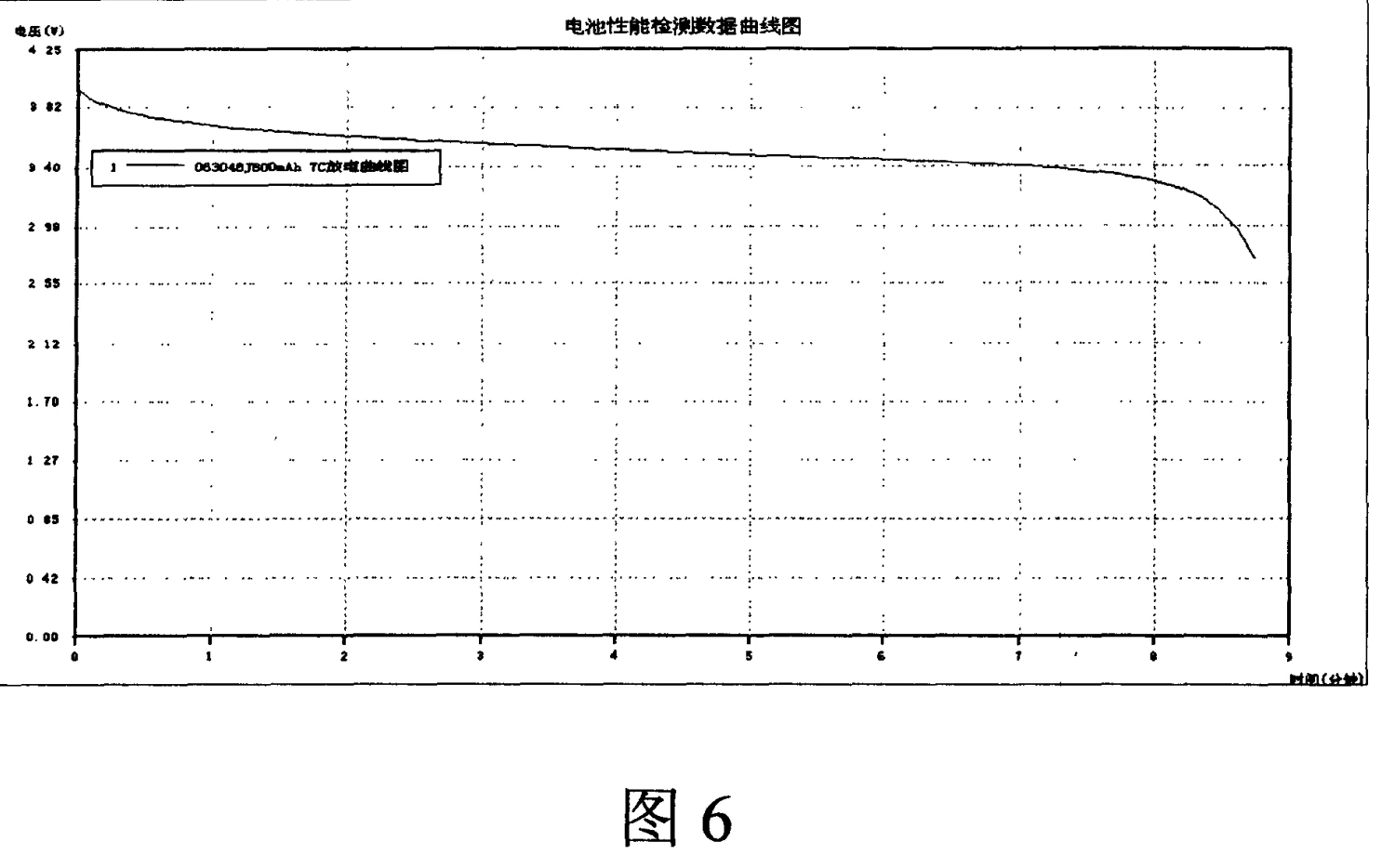
| 5C | 98% |
| 7C | 96% |
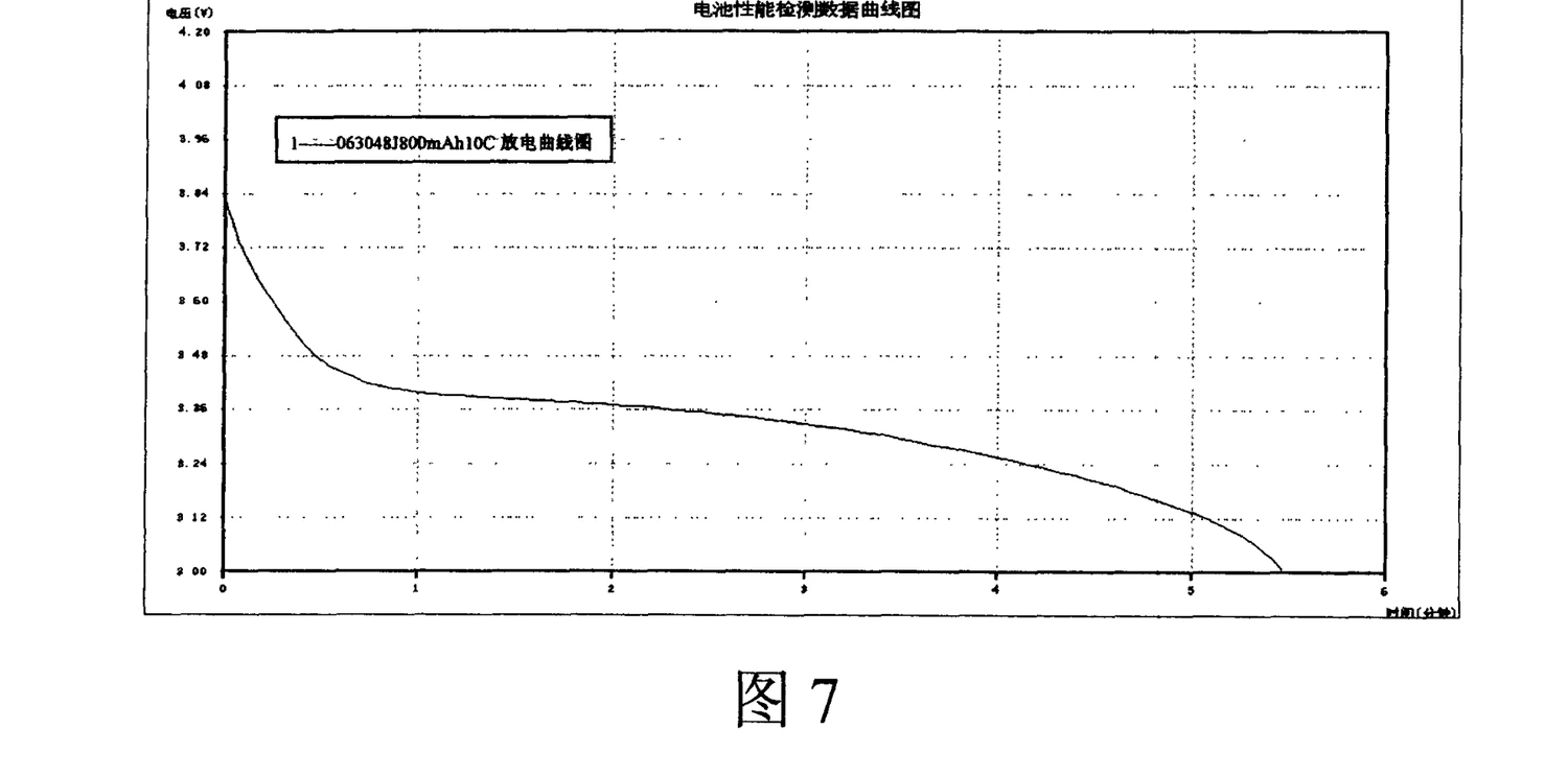
| 10C | 90% |
| 15C | 86% |
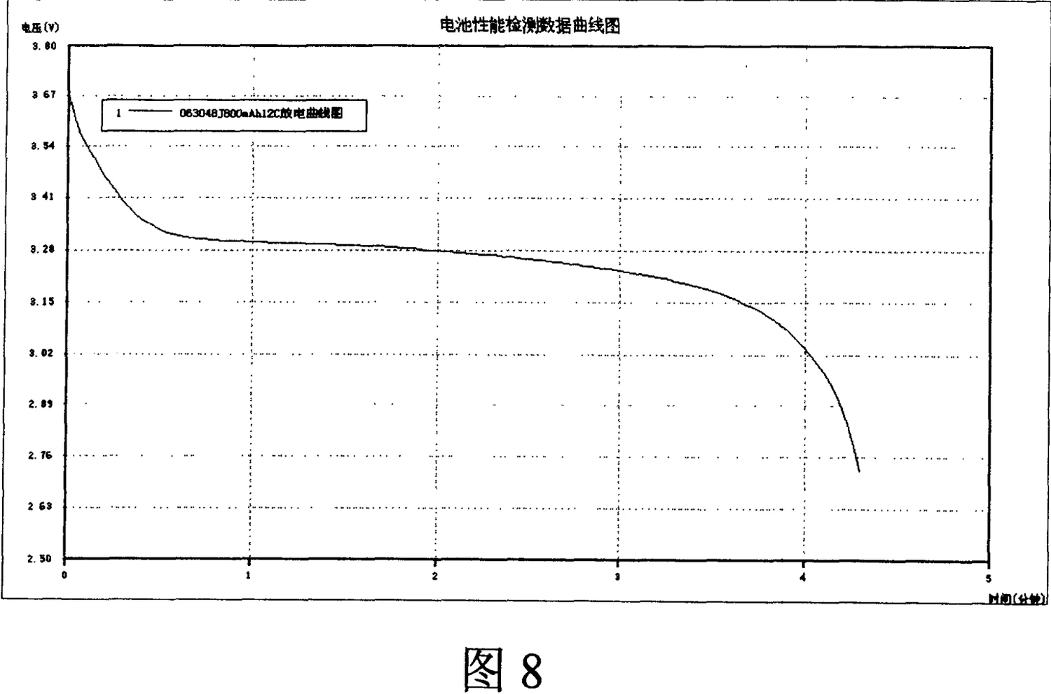
Het behouden van 86% van de nominale capaciteit bij 15C - een volledige ontlading in vier minuten - plaatste dit ontwerp ver boven het 1-3C-plafond van hedendaagse commerciële cellen, en boven de 12C-drempel die door modelvliegtuigtoepassingen werd vereist.
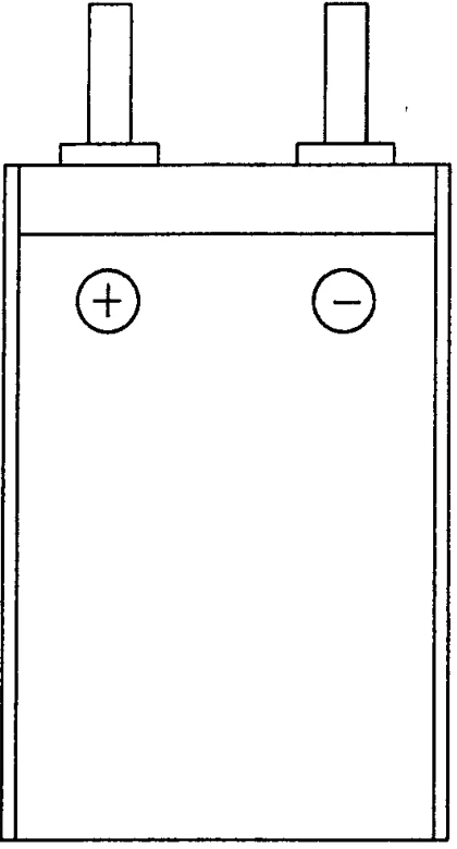
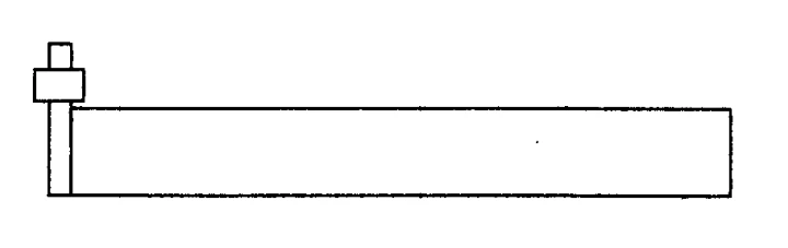
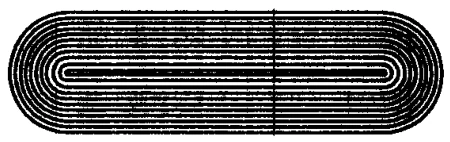
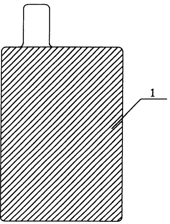
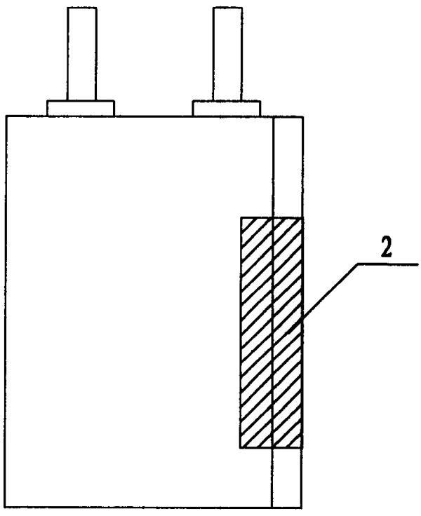
De gepubliceerde tekeningen bevatten gemeten ontlaadcurves bij 7C (Fig. 6), 10C (Fig. 7) en 12C (Fig. 8), naast schematische weergaven van de celconstructie (Fig. 1), de geometrie van de gewikkelde elektrode (Fig. 2-3) en de geometrie van de gestapelde elektrode (Fig. 4-5).
Ⅵ. Van een octrooi uit 2006 naar productieapparatuur in 2026
Het droge-premixprincipe in conclusie 10 bleef niet beperkt tot 2006.
Het verdelen van een geleidend middel over actieve deeltjes vóór contact met oplosmiddel is de conceptuele voorvader van wat de industrie nu droge-elektrodeproces noemt - de routes met minder of zonder oplosmiddel die momenteel worden opgeschaald voor energiezuinige en solid-state cellen.
TOB NEW ENERGY bouwt vandaag de dag apparatuur voor precies dat proces:
- Oplossing voor droge-elektrodefilm - vorming van elektrodefilm via de droge route
- Elektrodevoorbereiding - mengen, coaten, kalanderen
- Apparatuur voor solid-state batterijen - waar droge verwerking effectief verplicht is
De ingenieur die de aanpak uit 2006 mede heeft uitgevonden, leidt nu het team dat die apparatuur specificeert. Die continuïteit - laboratoriuminzicht in 2006, productiehardware in 2026 - is wat onze klanten kopen wanneer ze voor TOB kiezen.
Verken het volledige overzicht: alle octrooien van het technische team van TOB
Ⅶ. Veelgestelde vragen
Welke ontlaadsnelheid behaalt CN1819321A?
Het verhoogt het aanhoudende ontlaadvermogen van de 1-3C die typisch was voor commerciële cellen uit het 2006-tijdperk naar 12-15C. Het gemeten capaciteitsbehoud ten opzichte van 1C is 98% bij 5C, 96% bij 7C, 90% bij 10C en 86% bij 15C.
Wat is de belangrijkste productiestap in CN1819321A?
Droge-poederpremixing. Actief materiaal en geleidend middel worden als droge poeders gemengd onder bescherming van inert gas voordat de bindmiddeloplossing wordt toegevoegd, zodat het geleidende middel eerst over de oppervlakken van de actieve deeltjes wordt verdeeld. Dit vormt een continu geleidend netwerk in plaats van de willekeurige dispersie die door conventioneel nat mengen wordt geproduceerd.
Welke elektrode gebruikt welke formulering in CN1819321A?
De kathode (positief, op aluminiumfolie) gebruikt 75-93% actief materiaal, 1-20% geleidend middel en 2-9% bindmiddel. De anode (negatief, op koperfolie) gebruikt 90-97% actief materiaal, 0-3% geleidend middel en 2-6% bindmiddel. Automatische Engelse vertalingen van dit document, inclusief de door een machine gegenereerde samenvatting op Google Patents, draaien deze twee aanduidingen om.
Wie heeft CN1819321A uitgevonden en is TOB NEW ENERGY de eigenaar?
Het werd mede uitgevonden door Lei Yuanbing en Huang Zhengyao (Dany Huang) en in 2006 ingediend door Shenzhen Liduowei Batteries Co., Ltd. TOB NEW ENERGY, opgericht in 2012, bezit dit patent niet. Het is hier gepubliceerd als onderdeel van het gedocumenteerde uitvindingsdossier van Dr. Dany Huang; hij leidt nu het kerntechnische team van TOB.
Wat is de huidige juridische status van CN1819321A?
CN1819321A is een gepubliceerde uitvindingsaanvraag (soortcode A). Er is geen verleende B-publicatie in het openbare register te vinden. De maximale termijn van 20 jaar, gerekend vanaf de indieningsdatum van 6 maart 2006, is in maart 2026 verstreken. De technische openbaarmaking bevindt zich in het publieke domein en wordt hier ter referentie weergegeven.
Hoe verhoudt een patent uit 2006 zich tot de huidige apparatuur van TOB?
Het principe van droge voormenging is de conceptuele voorloper van moderne droge elektrodeprocessen, de route met gereduceerd oplosmiddel die nu wordt opgeschaald voor cellen met hoge energie en solid-state cellen. TOB NEW ENERGY bouwt apparatuur voor droge elektrodefilms en elektrodepreparatielijnen die deze aanpak industrialiseren, gespecificeerd door het team dat de mede-uitvinder nu leidt.
Ⅷ. Officieel dossier & tekeningen
- Google Patents - CN1819321A(volledige tekst, conclusies, 11 voorwaartse citaties)
- Officiële PDF met alle tekeningen
- Espacenet-dossier
 Abonneer u op ons